Mạch đo điện DC đa năng 200A giao tiếp RS485 Modbus PZEM-017 được sử dụng để đo và theo dõi gần như hoàn toàn các thông số về điện năng DC của hệ thống như điện áp hoạt động, dòng tiêu thụ, công suất và năng lượng tiêu thụ, mạch sử dụng giao tiếp RS485 Modbus chuẩn công nghiệp dễ dàng kết nối truyền dữ liệu tới PLC, Vi điều kiển hoặc máy tính, thích hợp cho các ứng dụng theo dõi năng lượng, IoT,...
Mạch đo điện DC đa năng 200A giao tiếp RS485 Modbus PZEM-017 nhỏ gọn, dễ lắp đặt, đi kèm trở Shunt lên đến 200A, mạch có chất lượng gia công và linh kiện tốt, độ bền cao.
Thông số kỹ thuật:
- Model: PZEM-017 kèm trở Shunt 200A
- Điện áp đo và hoạt động: 0.05~300VDC, sai số 0.01
- Dòng điện đo và hoạt động: 0.02 ~ 200A, sai số 0.01
- Công suất đo và hoạt động: 0.2 ~ 90kW, sai số 0.1
- Năng lượng đo và hoạt động: 0~9999kWh
- Giao tiếp RS485 Modbus baudrate mặc định 9600, 8, 1.
- Có opto cách ly an toàn giữa mạch đo và mạch nhận tín hiệu RS485 Modbus.
- Lưu giữ thông số năng lượng tiêu thụ trong bộ nhớ.
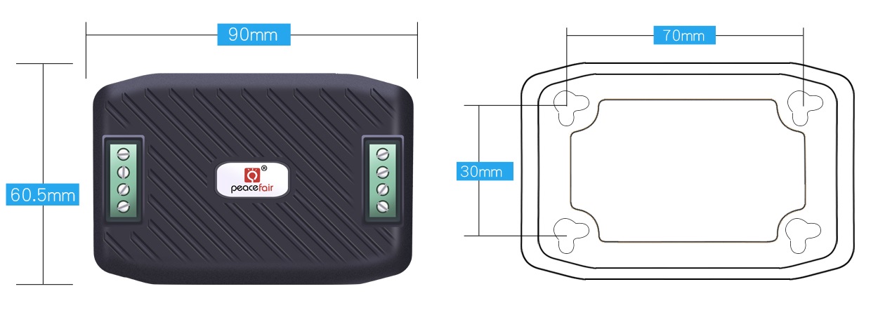
- Kích thước: 90 x 60.5 mm
Phần mềm kết nối máy tính.
Arduino example
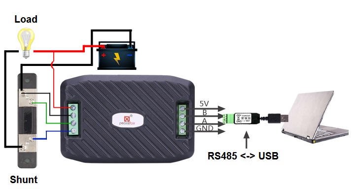
Sơ đồ kết nối:


Hướng dẫn lập trình:
2.1 Physical layer protocol
Physical layer use UART to RS485 communication interface.
Baud rate is 9600, 8 data bits, 2 stop bit, no parity.
2.2 Application layer protocol
The application layer use the Modbus-RTU protocol to communicate. At present, it only supports function codes such as 0x03 (Read Holding Register), 0x04 (Read Input Register), 0x06 (Write Single Register), 0x41 (Calibration), 0x42 (Reset energy).etc.
0x41 function code is only for internal use (address can be only 0xF8), used for factory calibration and return to factory maintenance occasions, after the function code to increase 16-bit password, the default password is 0x3721.
The address range of the slave is 0x01 ~ 0xF7. The address 0x00 is used as the broadcast address, the slave does not need to reply the master. The address 0xF8 is used as the general address, this address can be only used in single-slave environment and can be used for calibration etc.operation.
2.3 Read the measurement result
The command format of the master reads the measurement result is(total of 8 bytes):
Slave Address + 0x04 + Register Address High Byte + Register Address Low Byte + Number of Registers High Byte + Number of Registers Low Byte + CRC Check High Byte + CRC Check Low Byte.
The command format of the reply from the slave is divided into two kinds:
Correct Reply: Slave Address + 0x04 + Number of Bytes + Register 1 Data High Byte + Register 1 Data Low Byte + ... + CRC Check High Byte + CRC Check Low Byte
Error Reply: Slave address + 0x84 + Abnormal code + CRC check high byte + CRC check low byte
Abnormal code analyzed as following (the same below)
0x01,Illegal function;
0x02,Illegal address;
0x03,Illegal data;
0x04,Slave error.
The register of the measurement results is arranged as the following table
Register address Description Resolution
0x0000 Voltage value 1LSB correspond to 0.01V
0x0001 Current value 1LSB correspond to 0.01A
0x0002 Power value low 16 bits 1LSB correspond to 0.1W
0x0003 Power value high 16 bits
0x0004 Energy value low 16 bits 1LSB correspond to 1Wh
0x0005 Energy value high 16 bits
0x0006 High voltage alarm status 0xFFFF is alarm,0x0000 is not alarm
0x0007 Low voltage alarm status 0xFFFF is alarm,0x0000 is not alarm
For example, the master sends the following command (CRC check code is replaced by 0xHH and 0xLL, the same below):
0x01 + 0x04 + 0x00 + 0x00 + 0x00 + 0x08 + 0xHH + 0xLL
Indicates that the master needs to read 8 registers with slave address 0x01 and the start address of the register is 0x0000.
The correct reply from the slave is as following:
0x01 + 0x04 + 0x10 + 0x27 + 0x10 + 0x00 + 0x64 + 0x03 + 0xE8 + 0x00 + 0x00 + 0x00 + 0x00 + 0x00 + 0x00 + 0x00 + 0x00 + 0x00 + 0x00 + 0xHH + 0xLL
The above data shows
Voltage is 0x2710,converted to decimal is 10000,display 100.00V;
Current is 0x0064,converted to decimal is 100,display 1.00A;
Power is 0x000003E8,converted to decimal is 1000,display 100.0W;
Energy is 0x00000000,converted to decimal is 0,display 0Wh;
High voltage alarm status 0x0000,indicates the current voltage is lower than the high voltage threshold.
Low voltage alarm status 0x0000,indicates the current voltage is higher than the low voltage threshold.
2.4 Read and modify the slave parameters
At present,it only supports reading and modifying slave address and power alarm threshold
The register is arranged as the following table
Register address Description Resolution
0x0000 High voltage alarm threshold(5~350V),default is 300V 1LSB correspond to 0.01V
0x0001 Low voltage alarm threshold(1~350V),default is 7V 1LSB correspond to 0.01V
0x0002 Modbus-RTU address The range is 0x0001~0x00F7
0x0003 The current range(only for PZEM-017) 0x0000:100A
0x0001:50A
0x0002:200A
0x0003:300A
The command format of the master to read the slave parameters and read the measurement results are same(described in details in Section 3.3), only need to change the function code from 0x04 to 0x03.
The command format of the master to modify the slave parameters is (total of 8 bytes):
Slave Address + 0x06 + Register Address High Byte + Register Address Low Byte + Register Value High Byte + Register Value Low Byte + CRC Check High Byte + CRC Check Low Byte.
The command format of the reply from the slave is divided into two kinds:
Correct Response: Slave Address + 0x06 + Number of Bytes + Register Address Low Byte + Register Value High Byte + Register Value Low Byte + CRC Check High Byte + CRC Check Low Byte.
Error Reply: Slave address + 0x86 + Abnormal code + CRC check high byte + CRC check low byte.
For example, the master sets the slave's high voltage alarm threshold:
0x01 + 0x06 + 0x00 + 0x01 + 0x4E + 0x20 + 0xHH + 0xLL
Indicates that the master needs to set the 0x0001 register (low voltage alarm threshold) to 0x4E20(200.00V).
Set up correctly, the slave return to the data which is sent from the master.
For example, the master sets the low voltage alarm threshold of the slave
0x01 + 0x06 + 0x00 + 0x02 + 0x03 + 0xE8 + 0xHH + 0xLL
Indicates that the master needs to set the 0x0002 register (low voltage alarm threshold) to 0x03E8(10.00V).
Set up correctly, the slave return to the data which is sent from the master.
For example, the master sets the address of the slave
0x01 + 0x06 + 0x00 + 0x03 + 0x00 + 0x05 + 0xHH + 0xLL
Indicates that the master needs to set the 0x0003 register (Modbus-RTU address) to 0x0005
Set up correctly, the slave return to the data which is sent from the master.
2.5 Reset energy
The command format of the master to reset the slave's energy is (total 4 bytes):
Slave address + 0x42 + CRC check high byte + CRC check low byte.
Correct reply: slave address + 0x42 + CRC check high byte + CRC check low byte.
Error Reply: Slave address + 0xC2 + Abnormal code + CRC check high byte + CRC check low byte
2.6 Calibration
The command format of the master to calibrate the slave is (total 6 bytes):
0xF8 + 0x41 + 0x37 + 0x21 + CRC check high byte + CRC check low byte.
Correct reply: 0xF8 + 0x41 + 0x37 + 0x21 + CRC check high byte + CRC check low byte.
Error Reply: 0xF8 + 0xC1 + Abnormal code + CRC check high byte + CRC check low byte.
It should be noted that the calibration takes 3 to 4 seconds, after the master sends the command, if the calibration is successful, it will take 3 ~ 4 seconds to receive the response from the slave.
2.7 CRC check
CRC check use 16bits format, occupy two bytes, the generator polynomial is X16 + X15 + X2 +1, the polynomial value used for calculation is 0xA001.
The value of the CRC check is all results of a frame data checking divide CRC
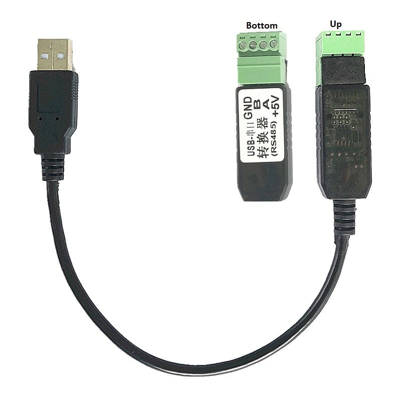
Lưu ý có thể mua thêm cáp chuyển USB to RS485 Converter chính hãng Peacefair như hình dưới đây với giá 95.000VNĐ:
Thông tin sản phẩm được Hshop.vn tự xây dựng, nếu sử dụng xin vui lòng ghi rõ nguồn, xin cảm ơn!


")
 V2")